Introduction: The Unique Challenges of Underwater Robotics

Pool cleaning robots represent one of the fastest-growing segments in marine and domestic service robotics. Unlike terrestrial vacuums, underwater cleaning robots operate in highly demanding environments involving direct water submersion, high static pressure, ambient chemical exposure (chlorine and salt water), and dynamic impeller load fluctuations.

At the heart of every cordless pool cleaner is its lithium battery system. The pack must not only power dual traction motors and high-flow filtration pumps, but also maintain precise weight-to-volume ratios for neutral buoyancy.

Choosing an improper battery design leads to short operational runtimes, seal failures, premature capacity fade in cold water, or false over-current shutdowns. This guide outlines how OEM/ODM engineering teams can specify the ultimate power system for pool cleaning robots.

Chemistry Comparison: NMC vs. LiFePO4 for Underwater Units

Selecting the optimal lithium-ion chemistry depends heavily on the robot’s form factor, weight constraints, and target deployment environment.

Technical ParameterNMC (Nickel Manganese Cobalt)LiFePO4 (Lithium Iron Phosphate)
Gravimetric Energy DensityHigh (220 – 260Wh/kg) — Allows lighter underwater weightModerate (140 – 170 Wh/kg)
Volumetric Energy DensitySuperior — Essential for sleek, low-drag hydrodynamicsModerate
Buoyancy ImpactMinimizes heavy ballast requirements for neutral buoyancyRequires structural buoyancy accommodation
Cycle Life (80% DOD)800 – 1,500cycles3,000 – 5,000cycles
Operating TemperatureNeeds low-temp heating below 0℃Thermal heating recommended below 5℃
Primary ApplicationCordless Residential Pool Robots, Compact CleanersCommercial/Industrial Pool Sweepers, Deep-Water Cleaners

Essential Engineering Requirements for Pool Robot Batteries

IP68 Submersible Sealing & Thermal Dissipation

Standard IP67 ingress protection is insufficient for continuous submersion. Pool robot batteries require IP68 sealing structures (rated for 2 – 5 meters submersion).

  • Double-O-Ring & Structural Potting: Utilizing custom aluminum or reinforced polycarbonate housings sealed with two-stage silicone potting to resist chlorine and salt corrosion.
  • Underwater Thermal Management: Water is an excellent heat sink, but static air trapped inside sealed battery compartments acts as an insulator. Implementing high-conductive Thermal Interface Materials (TIM) transfers heat efficiently from cells/BMS to the outer shell.

High-Rate Anti-Overcurrent Protection Algorithm

Pool cleaner impellers frequently encounter sudden torque spikes caused by leaf blockages, suction pressure changes on wall-climbing modes, or debris jam.

  • The Problem: Standard BMS hardware protection mistaking short motor torque surges for short circuits, causing the robot to stop unexpectedly in the middle of the pool.
  • The Solution: Our proprietary Smart BMS Anti-Overcurrent Algorithm uses dynamic current-time integrals  to differentiate between motor stall surges 3C-5C for 2-5 seconds and real electrical short circuits, eliminating false trips while ensuring absolute safety.

Low-Temperature Self-Heating Technology

Early morning water temperatures or winter storage environments, severely restrict lithium-ion charge acceptance and reduce discharge capacity. Integrated PTC low-temperature heating elements inside the pack automatically warm the cells before charging or under heavy load, extending cell lifespan and restoring full runtime.

Precise SOC Estimation & Auto-Docking Reliability

To prevent a pool robot from dying at the deep end, precise State of Charge (SOC) tracking is vital. Combining Coulomb counting with dynamic impedance compensation, the Smart BMS maintains an SOC accuracy within 2%, triggering an auto-surface or auto-docking sequence before energy runs out.

Smart BMS Communication Interfaces

Modern smart pool robots require real-time system monitoring. The Smart BMS integrates CANbus 2.0B, RS485, or UART protocols to report cell voltages, state of health (SOH), temperature profiles, and fault logs back to the robot’s main controller or mobile app.

End-to-End MES Traceability & Quality Control

For OEM/ODM brand owners, product reliability and safety are paramount. Every battery pack we manufacture is integrated into our Manufacturing Execution System (MES), providing complete digital traceability:

1. Cell Matching: 100% automated grading and sorting by voltage, capacity, and internal resistance.
2. Process Tracking: Laser welding parameters, screw torque logs, and thermal compound application are recorded per unique battery serial number.
3. End-of-Line (EOL) Validation: Comprehensive automated testing including high-potential insulation, 100% charge-discharge aging, and pressurized air/water leak detection.

Global Certifications & European Battery Passport Readiness

Exporting pool robots to global markets demands full regulatory compliance:

  • Transport & Air Safety: UN38.3, MSDS, and Drop-Test Certification.
  • International Electrical Safety: IEC 62133-2, UL 2271 (Light Electric Vehicle/Robotics), UL 2054, CE, FCC.
  • Environmental & EU Directives: Fully compliant with RoHS, REACH, and structured data tracking ready for the upcoming EU Digital Battery Passport under new EU battery regulations.

Frequently Asked Questions

Q1: How do you achieve IP68 waterproofing while maintaining heat dissipation in a pool battery?

A: We combine dual-seal O-rings with full silicone/epoxy potting inside a corrosion-resistant housing. Internal heat from the cells and Smart BMS MOSFETs is directed to the outer aluminum casing using high-thermal-conductivity interface pads, utilizing the surrounding pool water for passive cooling.

Q2: How does your Smart BMS handle motor stall currents from pool debris?

A: Our custom BMS firmware features an advanced anti-overcurrent algorithm. Instead of shutting down instantly during a sudden current spike, the system evaluates the duration and waveform of the surge. It allows temporary high-rate discharge (3C-5C for up to 5 seconds) to clear the block, while retaining instantaneous hardware protection for actual short circuits.

Q3: Can your battery packs be integrated into our factory MES for quality tracking?

A: Yes. Each battery pack carries a unique QR/barcode linked to our cloud-based MES database.

Partner with an Experienced OEM/ODM Battery Manufacturer

Engineering a custom underwater battery pack requires a balance of electrochemical selection, mechanical sealing, dynamic BMS programming, and industrial compliance.

Ready to power your next-generation pool cleaning robot?

Contact our engineering team today to receive a complete technical proposal and quotation within 48 hours.
In the rapidly evolving landscape of global electrification, energy density and unit cost are no longer the sole criteria for evaluating custom battery manufacturing partners. As international supply chains face geopolitical friction, raw material volatility, and tightening environmental standards, original equipment manufacturers (OEMs) and original design manufacturers (ODMs) face a dual challenge: ensuring uncompromising Battery Safety while maintaining high Supply Chain Resilience.

At Hypercell, we specialize in end-to-end custom battery pack design and precision manufacturing. Serving high-stakes industries—including medical devices, industrial automation, consumer electronics, and smart IoT networks—Hypercell integrates advanced battery safety engineering with robust, traceable supply chain systems to guarantee uninterrupted product performance and brand reliability.

Multi-Layered Battery Safety Architecture: Cell to BMS Integration

Safety is built into the fundamental chemistry, mechanical layout, and electronic controls of every custom Hypercell battery pack. Whether using Lithium Iron Phosphate (LiFePO4) for high thermal stability, high-density Cylindrical cells (18650 / 21700), or flexible Lithium-polymer (LiPo) form factors, our multi-tiered safety protocols mitigate risk across all operating conditions.

  • Thermal Isolation & Structural Integrity: Precision spacing between cells prevents single-cell thermal events from propagating across the pack. We utilize UL94-V0 flame-retardant structural frames, thermal pads, and impact-resistant enclosures.
  • Smart BMS Safeguards: Our custom Battery Management Systems (BMS) provide real-time monitoring of voltage, current, internal resistance, and temperature. Dual-layer hardware protection ensures backup shut-off in the event of firmware anomalies.
  • Scene-Driven Chemistry Matching: Matching cell chemistry (LiFePO4, Cylindrical, LiPo) precisely to the electrical and physical constraints of medical instruments, IoT nodes, or rugged industrial equipment.

Supply Chain Resilience & Manufacturing Traceability

A reliable battery design requires a secure, transparent supply chain. Hypercell leverages state-of-the-art automated production lines and digital tracking infrastructure to insulate B2B clients from market disruptions and quality defects.

Resilience DimensionTraditional Sourcing ModelHypercell OEM/ODM Advantage
Cell Sourcing & QVLSingle-vendor dependencyDual-sourcing strategic partners across LiFePO4, Cylindrical & LiPo cells
Manufacturing PrecisionManual assembly linesFully automated welding, sorting, and pack testing lines
Traceability & ExecutionBatch-level paper logsUnit-level digital Manufacturing Execution System (MES) tracking
Global ComplianceBasic regional testingUN38.3, IEC62133, UL1973, ISO9001, CE…

End-to-End MES Traceability
Hypercell’s proprietary Manufacturing Execution System (MES) tags every raw cell, BMS board, and connector with a unique barcode during incoming quality control (IQC). Throughout automated spot welding, capacity grading, and final aging tests, real-time parametric data is linked to the individual serial number. This enables complete product genealogy, targeted warranty tracking, and full compliance with global regulations such as the European Union’s Digital Battery Passport.

Comprehensive Testing & Global Certification Readiness

Bringing a custom medical device, IoT sensor, or industrial machine to global markets requires rapid, predictable certification pathways. Hypercell provides in-house validation using specialized testing equipment, including thermal shock chambers, automated cycle testers, vibration tables, high-voltage short-circuit simulators…

Our custom battery solutions are manufactured under strict ISO 9001 quality management systems and are engineered to meet international safety and transport standards.

  • UN 38.3 & MSDS: Guaranteed safe air and maritime transport compliance.
  • IEC 62133: International safety standard for portable sealed lithium secondary packs in consumer, IoT, and medical applications.
  • UL 1973: Safety standards for stationary energy storage and industrial motive battery systems.
  • CE, RoHS, REACH: Full environmental and electromagnetic compatibility for European and North American expansion.

Frequently Asked Questions

Q1: What customized battery solutions does Hypercell offer for OEM/ODM clients?

A: Hypercell provides end-to-end custom battery pack development, including custom BMS engineering, mechanical enclosure design, cell selection (LiFePO4, Cylindrical, LiPo), automated prototyping, full-scale manufacturing, and global certification support tailored for medical, industrial, consumer, and IoT applications.

Q2: How does Hypercell’s MES system enhance battery quality and supply chain safety?

A: Our MES tracks each component and production parameter (welding current, capacity test, voltage drift) in real time against a unique serial number. This ensures quality gatekeeping, root-cause traceability, and seamless audit compliance for B2B supply chain security.

Q3: Why choose LiFePO4 vs. Lithium-polymer (LiPo) for custom IoT or medical applications?

A: LiFePO4 is ideal for applications prioritizing ultra-long cycle life (2000+ cycles) and supreme thermal safety, such as medical carts and industrial equipment. Lithium-polymer (LiPo) offers high energy density and ultrathin, flexible form factors ideal for compact consumer electronics and slim IoT sensors. Hypercell engineers assist in selecting the optimal chemistry for your specific device requirements.

The European Commission has officially issued the Guidance Document: Digital Batteries Passport – data points by category (Ver. 1.0), marking a critical milestone for the EU Battery Regulation ((EU) 2023/1542). Outline 71 meticulous data points, this guidance establishes the technical blueprint for the mandatory Digital Battery Passport (DPP) effective February 18, 2027. As a specialized OEM/ODM manufacturer of custom Light Means of Transport (LMT) battery packs (e.g., e-scooters, e-bikes), Hypercell has successfully upgraded its factory MES (Manufacturing Execution System) and ERP infrastructure. Combined with its proprietary smart BMS dynamic data architecture, Hypercell provides global B2B clients with fully compliant custom battery solutions tailored for seamless market entry into Europe.

1. Key Takeaways of the EU Guidance for LMT Batteries

Under the latest European guidance, LMT batteries installed in e-scooters and e-bikes are prioritized for mandatory DPP implementation. Unlike standard industrial batteries, LMT batteries demand both “static supply chain traceability” and “dynamic operational monitoring”:

Data CategoryEU Guidance RequirementHypercell Compliance Capability
Basic Identification & TraceabilityUnique Identifier (UID) & ISO/IEC 15459 QR code, recording manufacturing date, GPS coordinates, and battery chemistryMES Automated Binding: Scanned QR tracking on the production line automatically syncs UID with MES logs
Critical Raw & Recycled MaterialsMandatory disclosure of recycled cobalt, lithium, and nickel ratios, plus raw material sourcingERP/SRM Closed-Loop Tracking: Upstream supplier coordination using Mass Balance accounting for recycled content
Dynamic Performance & Health (SOH)Real-time or periodic telemetry on capacity fade, internal resistance, cycle counts, and extreme conditionsIn-House Smart BMS: Advanced telemetry capabilities reading and outputting live SOH metrics via standardized API interfaces
Safety & Dismantling GuidelinesDetailed dismantling exploded diagrams, required tools, hazardous substances list (RoHS/REACH), and extinguishing agentsStandardized R&D Documentation: Comprehensive SDS manuals and English dismantling guides generated during the ODM phase

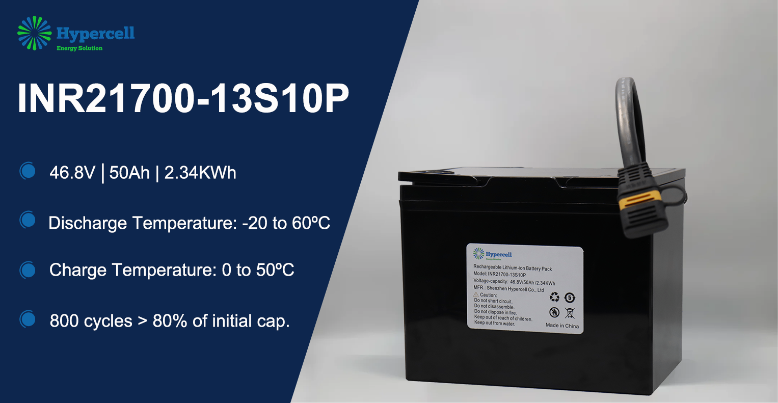
2. Case Study: Compliance in Action for the INR21700-13S10P Custom LMT Pack

ypercell INR21700-12S10P custom LMT battery pack with QR code for EU Battery Passport compliance

Highlighting Hypercell’s engineering excellence, the high-demand INR21700-13S10P custom battery pack (48V / 50Ah class), designed for European premium e-bikes and e-scooters, exemplifies complete DPP readiness across its lifecycle:

Factory-Level Digital ID (UID Integration):Including Hypercell’s manufacturing site location (GPS), battery weight, nominal energy (kWh), and official CE / UN38.3 certification records.
Proprietary BMS Telemetry for Dynamic Health:Equipped with Hypercell’s in-house developed BMS, the pack measures internal resistance (mΩ), cumulative throughput energy, and cycle counts during operation. Via CANbus/UART or integrated IoT modules, the BMS transmits real-time State of Health (SOH) updates to the DPP database—solving the primary compliance challenge for LMT brands.
Green Manufacturing & LCA Footprint Readiness:Leveraging ERP energy-monitoring modules, Hypercell provides a verified Cradle-to-Gate carbon footprint ledger compliant with ISO 14064 standards for every INR21700-13S10P unit produced.

3. Turnkey Compliance Roadmap for Global B2B Partners

To safeguard global OEM/ODM clients ahead of the 2027 enforcement deadline, Hypercell offers end-to-end regulatory support:

  1. ODM Custom Engineering: Tailoring voltage (36V / 48V / 52V), form factor, and smart BMS communication interfaces according to client specifications.
  2. Digital Production & Serialization: Binding component traceability to the final pack UID inside our MES system to ensure unalterable data authenticity.
  3. Data Interface & Cloud Integration: Assisting European brand owners in hosting battery data onto EU-approved DPP systems (such as Catena-X) for frictionless customs clearance.

Partner with Hypercell for EU Market Access

Hypercell is dedicated to driving sustainable mobility through engineering innovation and digital transparency.

We empower global e-mobility brands to overcome regulatory barriers and thrive in the European market.


UN38.3 refers to Section 38.3 of the United Nations Manual of Tests and Criteria. The standard ensures that lithium-ion and lithium metal batteries can safely withstand thermal, mechanical, and electrical stresses encountered during global transport without:

  1. Leaking hazardous materials
  2. Rupturing structural enclosures
  3. Experiencing thermal runaway or catching fire
  4. Disassembling or exploding

Failure to present verified UN38.3 test summary reports can result in immediate shipment rejection by air carriers, ocean freight handlers, customs clearance authorities, and international distribution logistics providers.

Why UN38.3 Matters for OEM Product Success

Integrating high-capacity battery packs without factoring in transportation clearance is a common pitfall in hardware development. A battery system may deliver high energy density and optimal runtime during operation, yet fail mechanical shock or altitude pressure simulations.
To secure global market access, OEM engineering teams must integrate transportation safety requirements directly into early-stage product requirements.

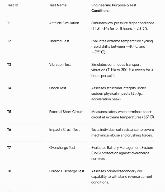
Required UN38.3 Test Sequence

UN38.3 testing requires battery cells and multi-cell packs to undergo a rigid series of environmental, mechanical, and electrical stress evaluations.

Target OEM Application Sectors

UN38.3 compliance is mandatory across all major battery-powered product categories:

  • Industrial Equipment & Robotics: Automated Guided Vehicles (AGVs), Autonomous Mobile Robots (AMRs), portable diagnostic equipment.
  • Medical Devices: Portable monitoring systems, mobile ventilators, surgical power tools.
  • UAV & Commercial Drones: Mapping equipment, inspection drones, defense systems.
  • IoT & Smart Infrastructure: Asset tracking devices, remote environmental monitors, smart utility meters.

Common Causes of UN38.3 Failure

  1. Subpar Cell Quality: Low-tier cells exhibit high internal resistance variations, leading to thermal instability under stress.
  2. Inadequate BMS Design: Weak protective circuitry fails to interrupt current during short-circuit (T5) or overcharge (T7) testing.
  3. Weak Mechanical Housing: Insufficient internal structural support leads to broken solder joints, disconnected nickel strips, or cracked outer enclosures during shock (T4) and vibration (T3) tests.
  4. Thermal Accumulation: Inadequate cell spacing traps heat, accelerating runaway during high-temperature short-circuit tests.

How Custom Battery Engineering Accelerates Compliance

Partnering with experienced custom battery engineering specialists mitigates certification risks and prevents redesign loops. Custom designs optimize performance through:

  • Integrated BMS Architectures: Custom-tuned firmware and hardware protections ensure instantaneous disconnects during overcharge and short-circuit conditions.
  • Advanced Thermal Barrier Engineering: Phase-change materials, thermal pads, and directional heat dissipation prevent cell-to-cell thermal propagation.
  • Ruggedized Structural Enclosures: Custom-molded housings and isolated cell holders absorb high-G impacts and continuous harmonic vibration.

Compliance Best Practices for OEMs

Do:

  • Select tier-1 cell manufacturers with per-certified base chemistry testing.
  • Integrate multi-tier BMS hardware protection logic.
  • Implement physical thermal barriers between high-energy density cells.
  • Work with experienced battery design partners early in the development cycle.
  • Maintain complete UN38.3 Test Summary documentation (per UN 38.3.5 requirements).

Avoid:

  • Using off-the-shelf, non-validated consumer-grade battery assemblies.
  • Postponing compliance design until late prototype stages.
  • Omitting structural vibration and shock resistance in internal pack geometry.

Frequently Asked Questions

1.Is UN38.3 certification mandatory globally?
Yes. International transport authorities including IATA, ICAO, IMO, and DOT mandate UN38.3 compliance for shipping lithium batteries by air, sea, rail, or road.

2.Does every custom battery configuration require its own UN38.3 test?
Yes. Any change to cell type, pack architecture, series-parallel configuration, enclosure design, or BMS protection scheme requires a new test sequence or official change evaluation.

3.How long does the UN38.3 certification process take?
Standard testing timelines typically range from 4 to 6 weeks, depending on laboratory availability, pre-test preparation, and battery cycle times for overcharge and thermal stability tests.

Whether holding inventory in a warehouse or shipping products internationally, ambient storage conditions and State-of-Charge (SoC) are the defining factors in battery safety, performance, and longevity. For most battery chemistries, cool and dry conditions around 15°C (59°F) are recommended for long-term storage. Depending on battery chemistry and product specifications, allowable storage temperatures may range from –40°C to 50°C for short-term exposure.
Based on industry testing standards, this guide provides a clear breakdown of storage protocols for Lithium-ion, Sealed Lead Acid (SLA), Nickel-based, and Alkaline batteries, as well as the latest IATA regulations regarding air transportation.

1. Lithium-ion (Li-ion): Ideal 40% SoC Storage and Sleep Mode Prevention

Lithium-ion chemistries are sensitive to voltage levels and ambient heat during long-term storage. Storing a Li-ion pack at 100% SoC in warm environments drastically accelerates permanent, unrecoverable capacity loss.

  • Optimal Storage State: approximately 40% SoC (typically 3.7–3.85V per cell depending on chemistry). This level minimizes chemical stress while allowing sufficient leeway for self-discharge.
  • Over-discharge & Copper Shunts: Most Li-ion batteries should not be stored below their manufacturer-specified discharge cutoff voltage, which is typically between 2.5V and 3.0V per cell. Many protection circuits may enter sleep mode when cell voltage approaches approximately 2.5VIf left below 2.0V/cell for an extended period, copper current collectors begin to dissolve, forming copper shunts that cause internal micro-shorts and severe thermal runaway risks upon recharge.

Engineering Tip: Before taking open-circuit voltage (OCV) readings, allow the battery to rest for 90 minutes to eliminate voltage bounce-back (the “rubber band effect”).

2. Air Transport Compliance (AirShip): The 30% SoC Mandate

In compliance with IATA and FAA regulations, all standalone or removable Lithium-ion battery packs transported via air cargo must be shipped at a maximum of 30% State-of-Charge.

  • Safety Rationale: Keeping batteries at or below 30% SoC significantly reduces volatility and energy release potential in the rare event of a thermal anomaly during transit.
  • Automated Shipping Prep: Modern industrial chargers and BMS platforms feature dedicated “AirShip” programs. Using Coulomb counting or advanced Kalman filters, these systems automatically charge or discharge packs to the precise 30% SoC threshold prior to packaging.

3. Sealed Lead Acid (SLA): Preventing Sulfation and The 70% SoC Recharging Rule

Sealed lead acid batteries can typically be stored for 6–24 months depending on storage conditions, provided they are monitored to prevent sulfation—an oxidation layer that builds up on negative plates due to low charge states.

  • Recharge Threshold: Apply a topping charge as soon as the battery drops to approximately 70% (2.07V/cell OCV or 12.42V for a 12V pack; specific gravity ~1.218).
  • Sulfation Reactivation: For small SLA cells (such as Hawker Cyclone) affected by prolonged storage, recovery is often possible by applying elevated voltage with a strictly limited low current to dissolve sulfate crystals back into active material.

4. Nickel-Based and Alkaline Batteries: Storage & Capacity Priming

  • Nickel-Based (NiMH / NiCd): Store at approximately 30–50% SoC or in a fully discharged state (for single cells). Nickel-metal-hydride can be stored for 3–5 years. Capacity drop during storage is largely reversible through 1–3 priming (charge/discharge) cycles.
  • Primary Alkaline Batteries: Alkaline batteries store well at cool room temperatures and ~50% relative humidity for up to 10 years. Avoid prolonged freezing conditions unless specified by the manufacturer, as extremely low temperatures may affect seals and performance.

Key Takeaways for Warehouse and Fleet Management Environment

Control: Keep storage areas cool (ideally 15°C / 59°F) and dry (~50% relative humidity). Avoid direct sunlight.
Li-ion Protocols: Store at 40% SoC for long-term inventory; in accordance with IATA Dangerous Goods Regulations, standalone lithium-ion batteries classified as UN3480 transported by air must not exceed 30% SoC.
Routine Maintenance: Check lead-acid voltages every 3–6 months and top-charge immediately if the pack drops below 12.42V.

Designing a custom battery pack requires balancing voltage, capacity, thermal safety, and cell consistency. Connecting battery cells in series increases overall terminal voltage, while parallel connections increase total amp-hour (Ah) capacity. Combining both in Series/Parallel (e.g., 4S2P) enables custom voltage and energy densities for medical devices, e-bikes, drones.

Fundamentals of Battery Cell Configurations: Series vs. Parallel

When engineering a custom battery pack, raw battery cells (such as 18650, 21700, or prismatic Li-ion cells) must be configured to meet the target system’s electrical requirements.

Cell Combination TypeNominal Voltage EffectCapacity (Ah) EffectPrimary Engineering Application
SeriesSum of cell voltagesRemains equal to 1 cellHigh-voltage tools
ParallelRemains equal to 1 cellSum of cell capacitiesHigh-runtime IoT devices, portable energy
Series/ParallelMultiplies cell voltageMultiplies cell capacityLaptops, medical equipment, roboticc…

Nominal Cell Voltages by Battery Chemistry

Selecting the right chemistry is the first step in custom OEM battery manufacturing. Each battery chemistry provides a specific nominal voltage:

  • Lithium-ion (NMC/LCO): 3.60V – 3.70V per cell (Standard for consumer electronics & high energy density)
  • Lithium Iron Phosphate (LiFePO4): 3.20V per cell (High safety, Typically 2,000–6,000 cycles depending on DoD and operating conditions.)
  • Lithium Titanate (LTO): 2.40V per cell (Ultra-fast charging & low-temperature tolerance)
  • Lead Acid: 2.00V per cell
  • Alkaline: 1.50V per cell
  • NiMH / NiCd: 1.20V per cell

Series Configurations for Higher Operating Voltages

Connecting cells in series (1S, 2S, 3S…nS) increases total voltage while keeping capacity (Ah) identical to a single cell.

The Weakest Link Phenomenon in Series Strings

In a series string, system performance is limited by the weakest cell:

  • During Discharge: The weak cell drains first, causing premature voltage drop and early device shutdown. Under extreme loads, potentially leading to cell reversal under severe over-discharge conditions.
  • During Charge: The low-capacity cell fills up first and enters an over-charge state longer than neighboring cells, generating heat and accelerating degradation.
4S series battery pack connection diagram showing 14.4V voltage cumulative and 3400mAh capacity

Source: Battery University

Parallel Configurations for Extended Capacity & Runtime

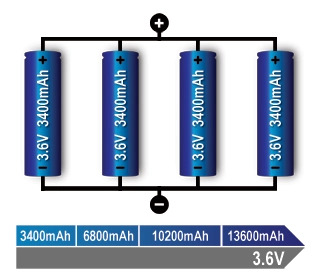
Connecting cells in parallel (1P, 2P, 3P…nP) boosts output capacity and continuous current delivery while maintaining the nominal cell voltage.

Key Considerations for Parallel Cell Engineering

  • Fault Tolerance: An open-circuit cell in parallel reduces capacity but allows system operation (similar to an engine running down one cylinder).
  • Internal Short Circuit Risks: A hard short-circuit inside a parallel cell causes adjacent cells to dump energy into the fault.
  • Protection Integration: Industrial OEM battery packs integrate individual cell fuses or micro-PTCs to disconnect shorted cells automatically before thermal runaway occurs.
1S4P parallel battery pack connection diagram showing 3.6V constant voltage and 13600mAh capacity expansion

Source: Battery University

Series/Parallel Combinations  & Pack Naming Conventions

Understanding 4S2P Architecture

In custom battery manufacturing, battery configurations are written with the series count first, followed by the parallel count (e.g., 4S2P).

  • Structure: 4 cells in series * 2 strings in parallel (8 total cells).
  • Electrical Output:
    Nominal Voltage: 3.6V* 4 = 14.4V
    Total Capacity: 2,400mAh * 2 = 4,800mAh
    Total Energy: 14.4V * 4.8 Ah = 69.12Wh

Partner with an Experienced Custom Battery Pack OEM/ODM

Need a tailored power solution for your product?
Contact our sales team today to review your project specifications, select the optimal cell architecture, and build a prototype custom battery pack.


When developing a high-performance device, a custom battery is far more than a power source. It directly influences system performance, safety, product lifespan, and regulatory compliance. For medical devices, industrial equipment, robotics, and IoT products, standard batteries often cannot meet demanding application requirements

At Hypercell, our custom battery solutions follow a highly disciplined, end-to-end engineering methodology. Backed by over 19 years of experience, here is our streamlined 6-step blueprint for bringing your power solution from initial concept to certified production.

Step 1: Discovery & Requirements Gathering

Every successful battery project begins with absolute clarity. Our engineering team collaborates directly with you to establish a comprehensive technical envelope:

Electrical Profiles:Nominal voltage, peak current draw, dynamic power profiles, charging requirements, and targeted capacity.
Mechanical Constraints:Exact 3D dimensions, enclosure materials, and connector interfaces.
Environmental Tolerances: Operating temperatures, vibration levels, humidity conditions, and ingress protection (IP ratings).

Step 2: Integrated Cells, Smart BMS & Mechanical Design

Once specifications are locked, we initiate the core design phase. We optimize the battery cell, Battery Management System (BMS), and mechanical enclosure as an integrated system.

  1. Cell & Chemistry Selection: We source from Tier-1 manufacturers, balancing energy density, cost, and lifecycle. Options include high-capacity Li-ion ,LiFePO4 or NiMH.
  2. Smart BMS Engineering: Protection functions include overcharge, over-discharge, overcurrent, short circuit, and temperature monitoring.We design custom PCBAs with precise State-of-Charge (SOC) tracking and integrated communication protocols (I2C, SMBus, CAN bus, or Modbus) so your device can read real-time battery diagnostics.
  3. hermal & Enclosure Design: Using 3D CAD, we engineer rugged enclosures focused on Thermal Management. We simulate stress to prevent thermal runaway propagation under heavy discharge curves.

Step 3: Rapid Prototyping & Rigorous Testing

Before committing to production-grade tooling, we construct functional, high-fidelity prototypes. Using in-house 3D printing and rapid spot-welding technology, we put the prototype through grueling physical and electrical stress tests:

Thermal Cycle Testing: Verifying pack integrity under extreme temperature swings.
Load & Capacity Testing: Simulating real-world device duty cycles to verify runtime.
Drop & Vibration Testing: Validating mechanical durability for industrial and military standards.

Step 4: Regulatory Compliance & Safety Certification

Navigating global approvals is one of the biggest bottlenecks in product launches. We partner with accredited third-party labs to secure crucial compliance certifications for your target market.

Step 5: Scaled Production & Quality Control

Once validated, your project transitions seamlessly into our advanced manufacturing facilities, where quality and consistency are prioritized:

Cell Matching: Sorting and pairing cells with identical internal resistance and capacity to maximize pack lifespan.
100% Automated EOL Testing: Every pack undergoes automated safety, protocol communication, and functional testing before packaging.
Full Traceability: End-to-end component tracking from BMS chipsets to individual lithium cells.

Step 6: Global Logistics & Class 9 Hazmat Compliance

The process doesn’t end when production finishes. Shipping lithium batteries requires navigating complex global regulatory frameworks, as they are classified as Class 9 Dangerous Goods (Hazmat).

Compliant Packaging: We design and supply UN-certified packaging (compliant with IATA, ADR, and IMDG codes).
Regulatory Documentation: We manage UN38.3 test summaries, Material Safety Data Sheets (MSDS), and shipper declarations.
Lifecycle Support: Ongoing supply chain management, future design revisions, and obsolescence tracking for critical components.


At Hypercell, we combine over 19 years of engineering expertise with state-of-the-art assembly to deliver safe, smart, and resilient power solutions.

Ready to kickstart your next project? Contact our sale today to discuss your custom power requirements!


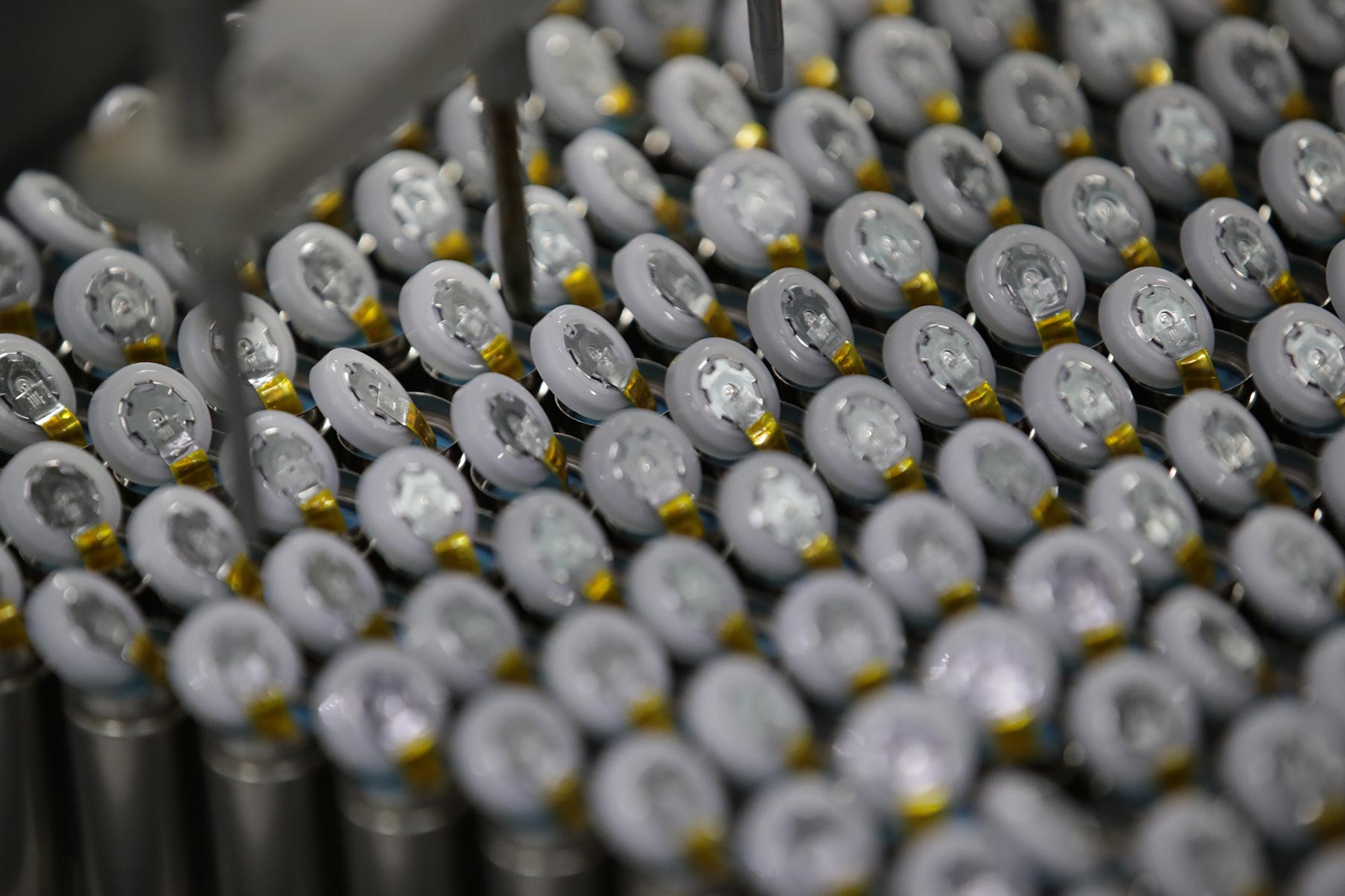
Explore Hypercell’s cylindrical lithium-ion battery production process, advanced manufacturing capabilities, and customized 18650 battery solutions.

How Are 18650 Batteries Manufactured?

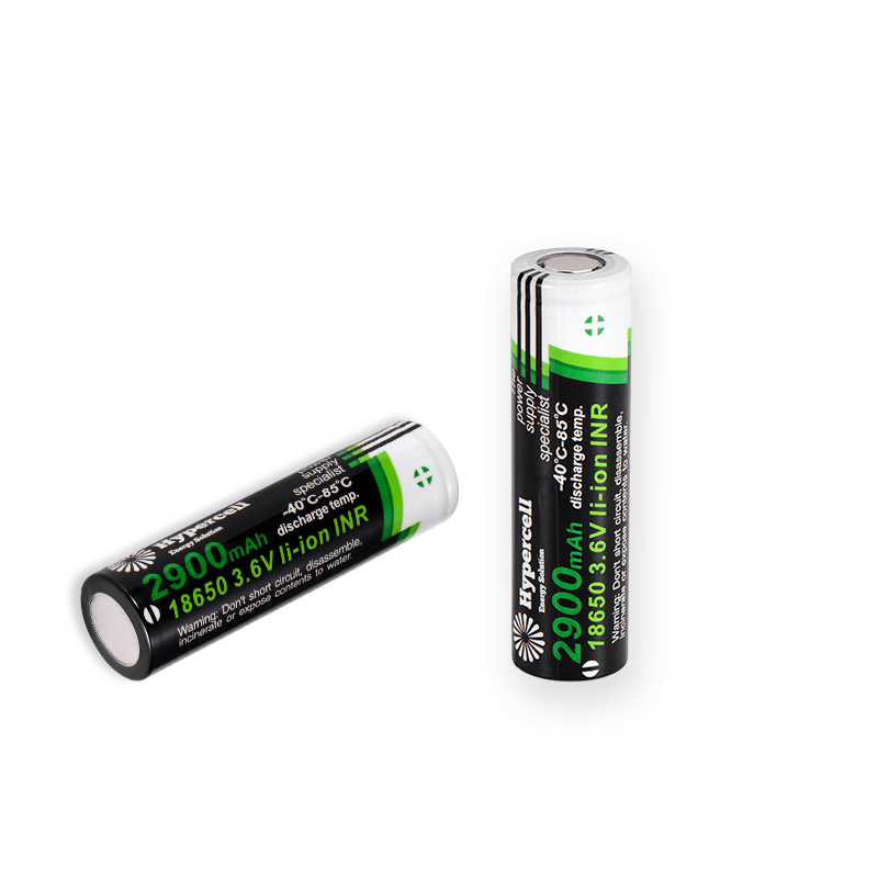
18650 lithium-ion batteries are widely used in power tools, consumer electronics, medical devices, industrial equipment, IoT devices, and battery pack applications due to their high energy density, reliability, and mature technology.

The manufacturing process requires precise control throughout electrode production, cell assembly, and quality inspection to ensure battery safety, performance, and consistency.Every manufacturing stage directly affects the battery’s energy density, cycle life, safety performance, and overall reliability

Hypercell provides customized 18650 lithium-ion battery solutions with professional manufacturing capabilities, advanced production equipment, and strict quality management systems.

18650 Battery Manufacturing Process

The production of an 18650 battery mainly includes five stages:

  • Raw Material Inspection
  • Electrode Manufacturing
  • Cylindrical Cell Assembly
  • Formation & Performance Testing
  • Digital Traceability & Quality Control

Stage 1: Raw Material Inspection & Preparation

Materials including cathode materials, anode materials, separators, electrolyte, and battery shells undergo strict incoming quality inspection before entering production.

Proper material management provides the foundation for stable battery performance and safety.

Stage 2: Electrode Manufacturing

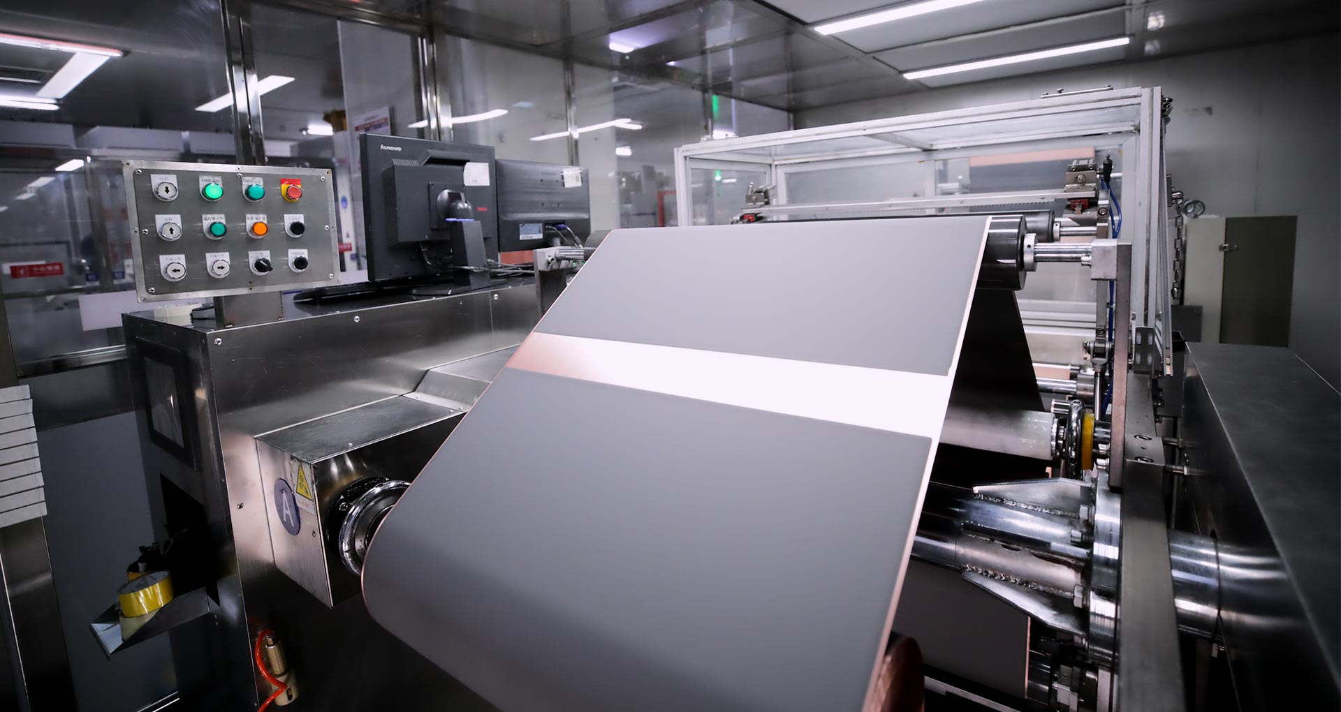
Electrode manufacturing begins with slurry preparation, where active materials, conductive additives, binders, and solvents are mixed into a uniform slurry. The cathode slurry is coated onto aluminum foil, while the anode slurry is coated onto copper foil through the electrode coating process.

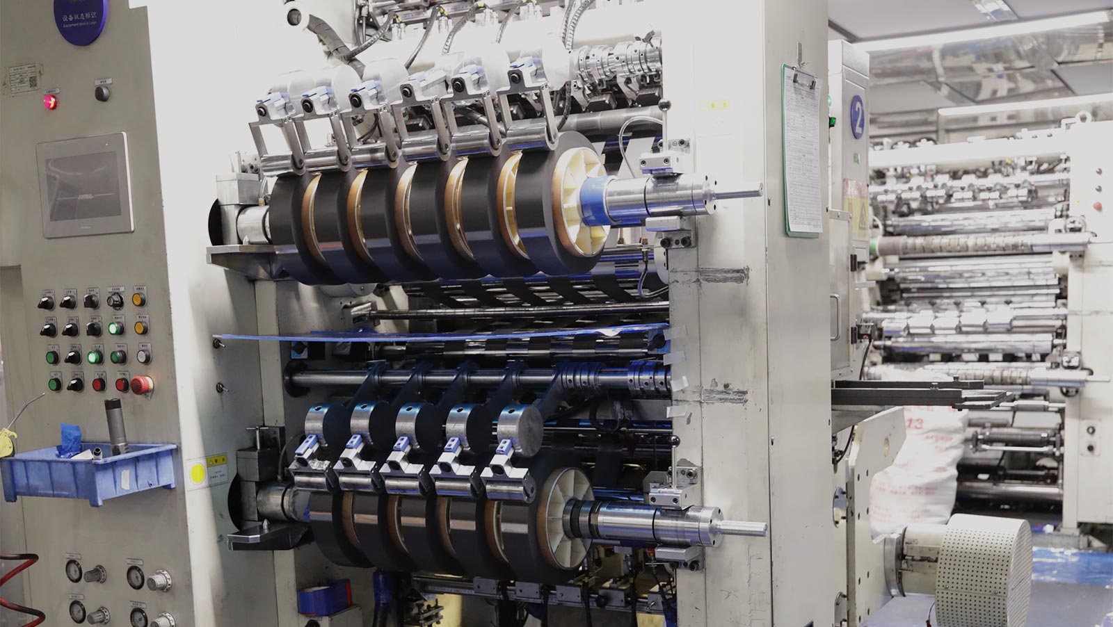
The coated electrodes then undergo drying to remove residual solvents, followed by calendaring to achieve the required thickness and electrode density. The electrodes are subsequently processed through slitting to obtain precise widths required for cell assembly.

Before entering the assembly stage, the electrode sheets undergo vacuum baking to remove residual moisture. Strict moisture control ensures better battery safety, improved cycle life, and long-term reliability.

Stage 3: Cylindrical Cell Assembly

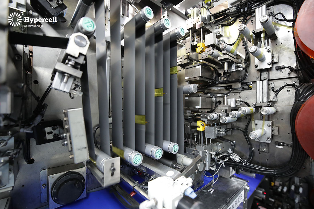
The positive electrode, separator, and negative electrode are precisely wound together to form a cylindrical jelly-roll structure. After winding, electrode tabs are welded to ensure reliable current collection. The jelly roll is then inserted into the cylindrical steel case

Next, a groove is mechanically formed near the top of the case during grooving to secure the internal structure, followed by electrolyte injection in a controlled low-humidity environment. After electrolyte injection, the cells undergo electrolyte soaking to ensure complete wetting of electrodes and separators, followed by controlled aging.

Finally, cell sealing is performed to hermetically seal the cell with a cap assembly that integrates a Current Interrupt Device (CID) and a safety vent, allowing the cells to safely proceed to the formation and testing stages.


Stage 4: Formation & Performance Testing

During formation, each cell undergoes controlled charge and discharge cycles to activate the electrochemical system and create a stable SEI layer on the anode surface. This process plays an important role in battery safety, cycle life, and long-term performance.

After formation, cells enter the aging stage under controlled environmental conditions. Aging helps evaluate voltage stability and identify potential defects before final inspection.

Each cell is tested for key parameters including capacity, voltage, internal resistance, and overall electrical performance. Cells are then graded according to performance characteristics to ensure consistency for battery pack assembly.

Stage 5: Digital Manufacturing & Traceability

Each battery cell is scanned and recorded through Hypercell’s MES-based digital production management system.

The traceability system tracks manufacturing information, inspection records, and production data to ensure complete quality control throughout the battery manufacturing process.

Digital traceability enables efficient quality management and supports reliable battery production for global customers.

Hypercell 18650 Battery Manufacturing Capability

As an experienced lithium-ion battery manufacturer, Hypercell provides customized cylindrical battery solutions from cell selection and battery design to mass production and quality validation.

Our capabilities include:

  • Cylindrical lithium-ion battery manufacturing
  • Custom battery pack development
  • Battery design support
  • BMS integration
  • Production quality control

With advanced manufacturing equipment, strict quality management, and complete production traceability, Hypercell delivers safe, reliable, and high-performance 18650 battery solutions.


Lithium-ion battery performance is not only determined by chemistry but also by how the internal electrodes are assembled. Among the most widely used manufacturing methods, stacking (lamination) and winding (jelly-roll) define the core structure of a battery cell.

While cylindrical batteries typically use winding technology and pouch cells mainly use stacking, prismatic batteries can adopt either process depending on performance and cost requirements.

Understanding these two technologies is essential for selecting the right battery solution for applications such as electric vehicles, medical devices, robotics, and consumer electronics.

Lithium-Ion Battery Manufacturing Overview

The battery manufacturing process generally includes four key stages:

  • Electrode slurry mixing
  • Coating, drying, calendaring, and slitting
  • Cell assembly (stacking or winding)
  • Electrolyte filling, formation, and grading

Among these, cell assembly is the most critical stage, as it directly determines the internal structure and performance of the battery.

What Is Winding Technology?

Winding technology, also known as the jelly-roll process, is the most mature lithium-ion battery assembly method.

In this process:

  • Positive electrode
  • Separator
  • Negative electrode

are continuously wound into a cylindrical or prismatic structure.

This creates a spiral internal structure commonly referred to as a “jelly roll.”

Applications of Winding Batteries

  • 18650 cells
  • 21700 cells
  • 4680 cylindrical cells
  • Power tools
  • Consumer electronics
  • Energy storage system

Advantages of Winding Technology

1. Highly mature manufacturing process
Winding has been developed over decades and is widely standardized.

2. High production efficiency
Continuous manufacturing enables large-scale automation.

3. Lower cost
Mature equipment and stable yield reduce overall production cost.

4. Excellent consistency
Suitable for mass production of standardized battery cells.

Limitations of Winding Technology

  • Internal stress concentration in jelly-roll structure
  • Limited space utilization due to cylindrical geometry
  • Slight constraints in energy density improvement

What Is Stacking Technology?

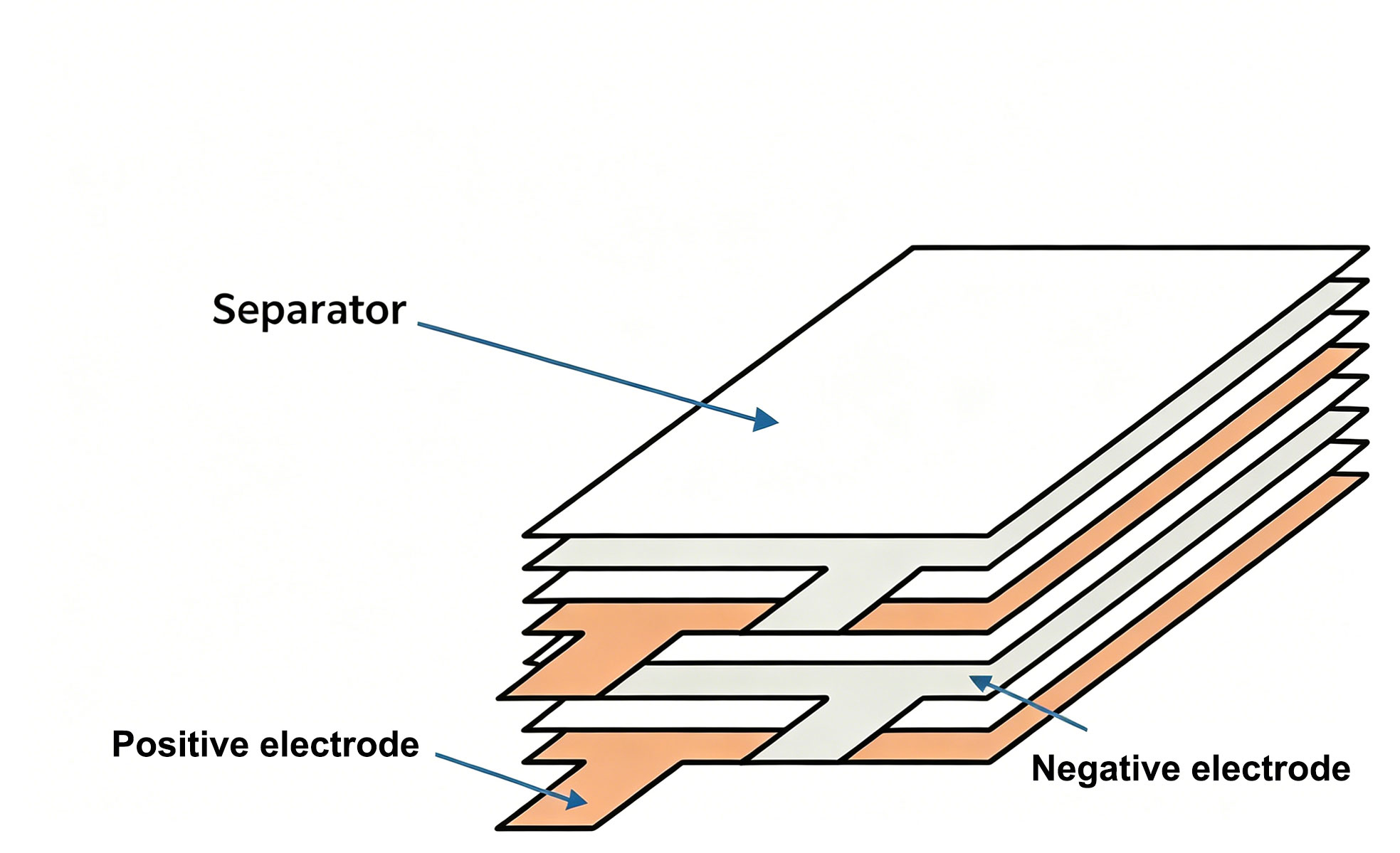
Stacking technology assembles electrodes by cutting them into individual sheets and stacking them layer by layer.

The typical structure is:

Positive electrode → Separator → Negative electrode → Separator → repeated stacking

This creates a flat and uniform electrode structure.

Applications of Stacked Batteries

  • High voltage batteries
  • Blade batteries
  • High-energy-density prismatic batteries
  • Drones
  • Medical devices
  • High-performance robotics

Advantages of Stacking Technology

1. Higher energy density potential
Better space utilization increases active material ratio.

2. Improved thermal management
More uniform heat distribution reduces hotspots.

3. Longer cycle life
Lower mechanical stress improves durability.

4. Enhanced safety performance
Reduced internal resistance and improved thermal stability.

5. Better fast-charging capability
Lower polarization improves charge acceptance.

Limitations of Stacking Technology

  • Higher equipment investment
  • Lower production efficiency compared to winding
  • More complex process control requirements

Stacking vs Winding: Key Differences


WindingStacking
Production EfficiencyHighMedium
Manufacturing CostLowerHigher
Energy DensityHighHigher
Cycle LifeLongLonger
Fast ChargingGoodBetter
Thermal ManagementGoodBetter
Safety PerformanceGoodBetter
Process ComplexityLowHigher
Equipment CostLowerHigher
ScalabilityExcellentGood


Why Stacking Offers Higher Energy Density

Stacking technology improves energy density through:

1. Better space utilization

No central void like cylindrical winding structures.

2. Higher active material ratio

Less inactive structural space inside the cell.

3. Uniform electrode alignment

Improves ion transport efficiency.

4. Reduced internal resistance

Shorter electron and ion pathways.

Fast Charging Performance Comparison

Fast charging performance is increasingly important in modern applications.

Stacked cells generally perform better because:

  • More uniform current distribution
  • Lower internal polarization
  • Better thermal stability during high-rate charging

This makes stacking ideal for:

  • Electric vehicles
  • Drones
  • High-performance industrial systems

Safety Considerations

Battery safety is influenced by both design and manufacturing precision.

Key safety factors include:

  • Burr control during electrode cutting
  • Separator integrity
  • Internal short-circuit prevention
  • Thermal runaway resistance

While both technologies can be safe when properly engineered, stacking often provides improved thermal uniformity in large-format cells.

Industry Applications

Winding Battery Applications

  • Power tools
  • Consumer electronics
  • Portable energy storage
  • Industrial equipment
  • Cylindrical battery platforms (18650 / 21700 / 4680)

Stacking Battery Applications

  • Electric vehicles
  • High-end drones
  • Medical devices
  • Robotics systems
  • High-energy-density prismatic batteries

Industry Trends

The lithium battery industry is evolving toward higher energy density and improved safety.

Key trends include:

  • Growth of large-format prismatic batteries
  • Increased adoption of stacking technology in EVs
  • Continued dominance of cylindrical winding cells in consumer and industrial applications
  • Development of high-speed stacking equipment

Companies such as Tesla continue to use winding-based cylindrical platforms like 4680 cells, while manufacturers like BYD promote blade battery designs based on stacked architectures.

How Hypercell Selects the Right Technology

At Hypercell, battery design is application-driven rather than technology-driven.

We evaluate multiple factors:

  • Energy density requirements
  • Discharge rate
  • Cycle life targets
  • Size and weight constraints
  • Operating environment
  • Cost efficiency

Based on these parameters, we select the most suitable cell architecture—whether winding or stacking—to ensure optimal performance for each application.

Frequently Asked Questions (FAQ)

1.Is stacking better than winding?

There is no absolute “better” option. The best choice depends on application requirements.

2.Why do cylindrical batteries use winding?

Because winding is highly efficient and well-suited to cylindrical geometry.

3.Why are pouch batteries usually stacked?

Stacking maximizes space utilization and improves energy density.

4.Which technology lasts longer?

Stacking may offer longer cycle life due to reduced mechanical stress, depending on design and usage conditions.

5.Is stacking more expensive?

Yes, due to higher equipment cost and lower production efficiency.

6.Can both technologies be used in prismatic batteries?

Yes, prismatic batteries can adopt either stacking or winding depending on design goals.

7.Which is better for fast charging?

Stacking generally performs better in high-rate charging applications.

Conclusion

Stacking and winding are two fundamental lithium-ion battery manufacturing technologies, each with distinct advantages.

Winding offers cost efficiency, mature production, and high scalability.
Stacking provides higher energy density, better thermal performance, and improved electrochemical stability.

The optimal choice depends entirely on application requirements rather than a universal superiority of one technology.

At Hypercell, we provide customized lithium battery solutions tailored to performance, safety, and cost objectives across diverse industries.

Learn what 1C, 3C, and 5C charging rates mean, how battery C-rates are calculated, and how fast charging impacts battery performance, safety, and lifespan. A practical guide for lithium battery applications and custom battery pack design.

What Is a Battery Charging C-Rate?

A battery C-rate indicates how quickly a battery is charged or discharged relative to its rated capacity.

The formula is:

C Rate=  Charging Current  ⁄  Battery Capacity

For example:

Battery CapacityCharging CurrentC-Rate
2000mAh2A1C
2000mAh6A3C
2000mAh10A5C

A higher C-rate means faster charging but also places greater stress on the battery.


Quick Comparison: 1C vs 3C vs 5C Charging

Charging RateFull Charge Time*Battery StressTypical Applications
1C~60 minLowSmartphones, consumer electronics
3C~20 minMediumFast-charging devices, portable power stations
5C~12 minHighEV fast charging, drones, industrial equipment

*Actual charging time varies depending on charging profiles and battery management systems (BMS).


What Is 1C Charging?

1C charging means the charging current equals the battery’s rated capacity.

Example:

  • 2000mAh battery → 2A charging current
  • 50Ah battery → 50A charging current

Advantages

  • Lowest heat generation
  • Longest battery lifespan
  • High charging efficiency
  • Better long-term reliability

Typical Applications

  • Consumer electronics
  • Medical equipment
  • Backup power systems

What Is 3C Charging?

3C charging delivers a current three times the battery capacity.

Example:

  • 2000mAh battery → 6A
  • 50Ah battery → 150A

Advantages

  • Faster charging
  • Balanced performance and longevity
  • Widely adopted in modern electronics

Common Applications

  • Fast-charging smartphones
  • Portable power stations
  • E-bikes
  • Energy storage systems

What Is 5C Charging?

5C charging is considered ultra-fast charging.

Example:

  • 2000mAh battery → 10A
  • 50Ah battery → 250A

Benefits

  • Extremely short charging times
  • Reduced downtime
  • Improved operational efficiency

Challenges

  • Increased heat generation
  • Higher material requirements
  • More complex battery management systems
  • Faster long-term battery degradation

Can All Lithium Batteries Support 5C Charging?

No.

Only specially designed high-rate lithium batteries can safely support 5C charging.

These batteries often require:

  • Advanced electrode materials
  • Optimized cell design
  • High-performance electrolytes
  • Intelligent Battery Management Systems (BMS)
  • Enhanced thermal management solutions

Attempting to charge a standard lithium battery at 5C may cause overheating, swelling, reduced cycle life, or safety risks.


How Does Charging Rate Affect Battery Life?

Generally:

Charging RateExpected Impact on Cycle Life
1CMinimal impact
3CModerate impact
5CSignificant impact if used frequently

Selecting the optimal charging rate depends on balancing charging speed, safety, and battery longevity.


Applications of Different C-Rates Across Industries

Consumer Electronics

Typically 1C–3C charging for smartphones, tablets, and wearables.

Medical Devices

Generally 0.5C–1C to maximize reliability and lifespan.

Drones and Robotics

Often require 3C–5C charging for rapid deployment.

Electric Vehicles

Modern EV batteries increasingly support 3C–5C fast charging technologies.

Industrial Equipment

Customized battery packs may use high-rate charging solutions to minimize operational downtime.


FAQ

What does 1C mean in a battery?

1C means the charging or discharging current equals the battery’s rated capacity, allowing a theoretical full charge in one hour.

Is 5C charging safe?

Yes, but only for batteries specifically designed for high-rate charging and equipped with proper thermal management and BMS protection.

Does fast charging damage lithium batteries?

Higher charging rates generate more heat and stress, which can accelerate aging over time. However, modern batteries and BMS designs significantly reduce these effects.

Which charging rate is best?

  • 1C for maximum lifespan
  • 3C for balanced performance
  • 5C for ultra-fast charging applications