
Custom Lithium-ion Battery Pack Design: Serie /Parallel Configurations Guide
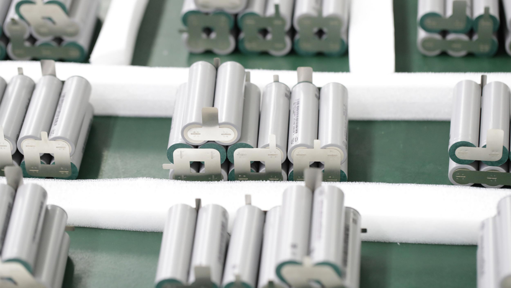
Designing a custom battery pack requires balancing voltage, capacity, thermal safety, and cell consistency. Connecting battery cells in series increases overall terminal voltage, while parallel connections increase total amp-hour (Ah) capacity. Combining both in Series/Parallel (e.g., 4S2P) enables custom voltage and energy densities for medical devices, e-bikes, drones.
Fundamentals of Battery Cell Configurations: Series vs. Parallel
When engineering a custom battery pack, raw battery cells (such as 18650, 21700, or prismatic Li-ion cells) must be configured to meet the target system’s electrical requirements.
| Cell Combination Type | Nominal Voltage Effect | Capacity (Ah) Effect | Primary Engineering Application |
| Series | Sum of cell voltages | Remains equal to 1 cell | High-voltage tools |
| Parallel | Remains equal to 1 cell | Sum of cell capacities | High-runtime IoT devices, portable energy |
| Series/Parallel | Multiplies cell voltage | Multiplies cell capacity | Laptops, medical equipment, roboticc… |
Nominal Cell Voltages by Battery Chemistry
Selecting the right chemistry is the first step in custom OEM battery manufacturing. Each battery chemistry provides a specific nominal voltage:
- Lithium-ion (NMC/LCO): 3.60V – 3.70V per cell (Standard for consumer electronics & high energy density)
- Lithium Iron Phosphate (LiFePO4): 3.20V per cell (High safety, Typically 2,000–6,000 cycles depending on DoD and operating conditions.)
- Lithium Titanate (LTO): 2.40V per cell (Ultra-fast charging & low-temperature tolerance)
- Lead Acid: 2.00V per cell
- Alkaline: 1.50V per cell
- NiMH / NiCd: 1.20V per cell
Series Configurations for Higher Operating Voltages
Connecting cells in series (1S, 2S, 3S…nS) increases total voltage while keeping capacity (Ah) identical to a single cell.
The Weakest Link Phenomenon in Series Strings
In a series string, system performance is limited by the weakest cell:
- During Discharge: The weak cell drains first, causing premature voltage drop and early device shutdown. Under extreme loads, potentially leading to cell reversal under severe over-discharge conditions.
- During Charge: The low-capacity cell fills up first and enters an over-charge state longer than neighboring cells, generating heat and accelerating degradation.

Source: Battery University
Parallel Configurations for Extended Capacity & Runtime
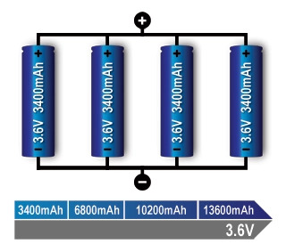
Connecting cells in parallel (1P, 2P, 3P…nP) boosts output capacity and continuous current delivery while maintaining the nominal cell voltage.
Key Considerations for Parallel Cell Engineering
- Fault Tolerance: An open-circuit cell in parallel reduces capacity but allows system operation (similar to an engine running down one cylinder).
- Internal Short Circuit Risks: A hard short-circuit inside a parallel cell causes adjacent cells to dump energy into the fault.
- Protection Integration: Industrial OEM battery packs integrate individual cell fuses or micro-PTCs to disconnect shorted cells automatically before thermal runaway occurs.
Source: Battery University
Series/Parallel Combinations & Pack Naming Conventions
Understanding 4S2P Architecture
In custom battery manufacturing, battery configurations are written with the series count first, followed by the parallel count (e.g., 4S2P).
- Structure: 4 cells in series * 2 strings in parallel (8 total cells).
- Electrical Output:
Nominal Voltage: 3.6V* 4 = 14.4V
Total Capacity: 2,400mAh * 2 = 4,800mAh
Total Energy: 14.4V * 4.8 Ah = 69.12Wh
Partner with an Experienced Custom Battery Pack OEM/ODM
Need a tailored power solution for your product?
Contact our sales team today to review your project specifications, select the optimal cell architecture, and build a prototype custom battery pack.