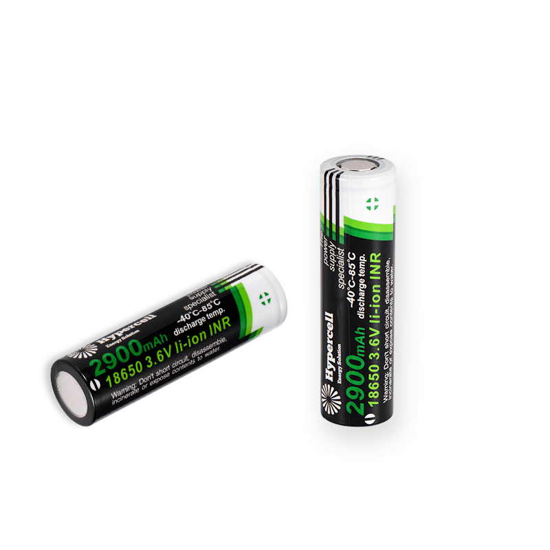
Whether holding inventory in a warehouse or shipping products internationally, ambient storage conditions and State-of-Charge (SoC) are the defining factors in battery safety, performance, and longevity. For most battery chemistries, cool and dry conditions around 15°C (59°F) are recommended for long-term storage. Depending on battery chemistry and product specifications, allowable storage temperatures may range from –40°C to 50°C for short-term exposure.
Based on industry testing standards, this guide provides a clear breakdown of storage protocols for Lithium-ion, Sealed Lead Acid (SLA), Nickel-based, and Alkaline batteries, as well as the latest IATA regulations regarding air transportation.

1. Lithium-ion (Li-ion): Ideal 40% SoC Storage and Sleep Mode Prevention

Lithium-ion chemistries are sensitive to voltage levels and ambient heat during long-term storage. Storing a Li-ion pack at 100% SoC in warm environments drastically accelerates permanent, unrecoverable capacity loss.

  • Optimal Storage State: approximately 40% SoC (typically 3.7–3.85V per cell depending on chemistry). This level minimizes chemical stress while allowing sufficient leeway for self-discharge.
  • Over-discharge & Copper Shunts: Most Li-ion batteries should not be stored below their manufacturer-specified discharge cutoff voltage, which is typically between 2.5V and 3.0V per cell. Many protection circuits may enter sleep mode when cell voltage approaches approximately 2.5VIf left below 2.0V/cell for an extended period, copper current collectors begin to dissolve, forming copper shunts that cause internal micro-shorts and severe thermal runaway risks upon recharge.

Engineering Tip: Before taking open-circuit voltage (OCV) readings, allow the battery to rest for 90 minutes to eliminate voltage bounce-back (the “rubber band effect”).

2. Air Transport Compliance (AirShip): The 30% SoC Mandate

In compliance with IATA and FAA regulations, all standalone or removable Lithium-ion battery packs transported via air cargo must be shipped at a maximum of 30% State-of-Charge.

  • Safety Rationale: Keeping batteries at or below 30% SoC significantly reduces volatility and energy release potential in the rare event of a thermal anomaly during transit.
  • Automated Shipping Prep: Modern industrial chargers and BMS platforms feature dedicated “AirShip” programs. Using Coulomb counting or advanced Kalman filters, these systems automatically charge or discharge packs to the precise 30% SoC threshold prior to packaging.

3. Sealed Lead Acid (SLA): Preventing Sulfation and The 70% SoC Recharging Rule

Sealed lead acid batteries can typically be stored for 6–24 months depending on storage conditions, provided they are monitored to prevent sulfation—an oxidation layer that builds up on negative plates due to low charge states.

  • Recharge Threshold: Apply a topping charge as soon as the battery drops to approximately 70% (2.07V/cell OCV or 12.42V for a 12V pack; specific gravity ~1.218).
  • Sulfation Reactivation: For small SLA cells (such as Hawker Cyclone) affected by prolonged storage, recovery is often possible by applying elevated voltage with a strictly limited low current to dissolve sulfate crystals back into active material.

4. Nickel-Based and Alkaline Batteries: Storage & Capacity Priming

  • Nickel-Based (NiMH / NiCd): Store at approximately 30–50% SoC or in a fully discharged state (for single cells). Nickel-metal-hydride can be stored for 3–5 years. Capacity drop during storage is largely reversible through 1–3 priming (charge/discharge) cycles.
  • Primary Alkaline Batteries: Alkaline batteries store well at cool room temperatures and ~50% relative humidity for up to 10 years. Avoid prolonged freezing conditions unless specified by the manufacturer, as extremely low temperatures may affect seals and performance.

Key Takeaways for Warehouse and Fleet Management Environment

Control: Keep storage areas cool (ideally 15°C / 59°F) and dry (~50% relative humidity). Avoid direct sunlight.
Li-ion Protocols: Store at 40% SoC for long-term inventory; in accordance with IATA Dangerous Goods Regulations, standalone lithium-ion batteries classified as UN3480 transported by air must not exceed 30% SoC.
Routine Maintenance: Check lead-acid voltages every 3–6 months and top-charge immediately if the pack drops below 12.42V.

Designing a custom battery pack requires balancing voltage, capacity, thermal safety, and cell consistency. Connecting battery cells in series increases overall terminal voltage, while parallel connections increase total amp-hour (Ah) capacity. Combining both in Series/Parallel (e.g., 4S2P) enables custom voltage and energy densities for medical devices, e-bikes, drones.

Fundamentals of Battery Cell Configurations: Series vs. Parallel

When engineering a custom battery pack, raw battery cells (such as 18650, 21700, or prismatic Li-ion cells) must be configured to meet the target system’s electrical requirements.

Cell Combination TypeNominal Voltage EffectCapacity (Ah) EffectPrimary Engineering Application
SeriesSum of cell voltagesRemains equal to 1 cellHigh-voltage tools
ParallelRemains equal to 1 cellSum of cell capacitiesHigh-runtime IoT devices, portable energy
Series/ParallelMultiplies cell voltageMultiplies cell capacityLaptops, medical equipment, roboticc…

Nominal Cell Voltages by Battery Chemistry

Selecting the right chemistry is the first step in custom OEM battery manufacturing. Each battery chemistry provides a specific nominal voltage:

  • Lithium-ion (NMC/LCO): 3.60V – 3.70V per cell (Standard for consumer electronics & high energy density)
  • Lithium Iron Phosphate (LiFePO4): 3.20V per cell (High safety, Typically 2,000–6,000 cycles depending on DoD and operating conditions.)
  • Lithium Titanate (LTO): 2.40V per cell (Ultra-fast charging & low-temperature tolerance)
  • Lead Acid: 2.00V per cell
  • Alkaline: 1.50V per cell
  • NiMH / NiCd: 1.20V per cell

Series Configurations for Higher Operating Voltages

Connecting cells in series (1S, 2S, 3S…nS) increases total voltage while keeping capacity (Ah) identical to a single cell.

The Weakest Link Phenomenon in Series Strings

In a series string, system performance is limited by the weakest cell:

  • During Discharge: The weak cell drains first, causing premature voltage drop and early device shutdown. Under extreme loads, potentially leading to cell reversal under severe over-discharge conditions.
  • During Charge: The low-capacity cell fills up first and enters an over-charge state longer than neighboring cells, generating heat and accelerating degradation.
4S series battery pack connection diagram showing 14.4V voltage cumulative and 3400mAh capacity

Source: Battery University

Parallel Configurations for Extended Capacity & Runtime

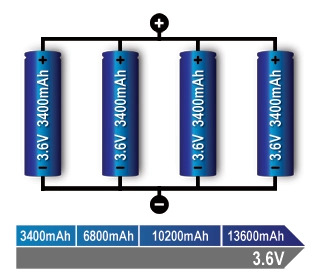
Connecting cells in parallel (1P, 2P, 3P…nP) boosts output capacity and continuous current delivery while maintaining the nominal cell voltage.

Key Considerations for Parallel Cell Engineering

  • Fault Tolerance: An open-circuit cell in parallel reduces capacity but allows system operation (similar to an engine running down one cylinder).
  • Internal Short Circuit Risks: A hard short-circuit inside a parallel cell causes adjacent cells to dump energy into the fault.
  • Protection Integration: Industrial OEM battery packs integrate individual cell fuses or micro-PTCs to disconnect shorted cells automatically before thermal runaway occurs.
1S4P parallel battery pack connection diagram showing 3.6V constant voltage and 13600mAh capacity expansion

Source: Battery University

Series/Parallel Combinations  & Pack Naming Conventions

Understanding 4S2P Architecture

In custom battery manufacturing, battery configurations are written with the series count first, followed by the parallel count (e.g., 4S2P).

  • Structure: 4 cells in series * 2 strings in parallel (8 total cells).
  • Electrical Output:
    Nominal Voltage: 3.6V* 4 = 14.4V
    Total Capacity: 2,400mAh * 2 = 4,800mAh
    Total Energy: 14.4V * 4.8 Ah = 69.12Wh

Partner with an Experienced Custom Battery Pack OEM/ODM

Need a tailored power solution for your product?
Contact our sales team today to review your project specifications, select the optimal cell architecture, and build a prototype custom battery pack.


When developing a high-performance device, a custom battery is far more than a power source. It directly influences system performance, safety, product lifespan, and regulatory compliance. For medical devices, industrial equipment, robotics, and IoT products, standard batteries often cannot meet demanding application requirements

At Hypercell, our custom battery solutions follow a highly disciplined, end-to-end engineering methodology. Backed by over 19 years of experience, here is our streamlined 6-step blueprint for bringing your power solution from initial concept to certified production.

Step 1: Discovery & Requirements Gathering

Every successful battery project begins with absolute clarity. Our engineering team collaborates directly with you to establish a comprehensive technical envelope:

Electrical Profiles:Nominal voltage, peak current draw, dynamic power profiles, charging requirements, and targeted capacity.
Mechanical Constraints:Exact 3D dimensions, enclosure materials, and connector interfaces.
Environmental Tolerances: Operating temperatures, vibration levels, humidity conditions, and ingress protection (IP ratings).

Step 2: Integrated Cells, Smart BMS & Mechanical Design

Once specifications are locked, we initiate the core design phase. We optimize the battery cell, Battery Management System (BMS), and mechanical enclosure as an integrated system.

  1. Cell & Chemistry Selection: We source from Tier-1 manufacturers, balancing energy density, cost, and lifecycle. Options include high-capacity Li-ion ,LiFePO4 or NiMH.
  2. Smart BMS Engineering: Protection functions include overcharge, over-discharge, overcurrent, short circuit, and temperature monitoring.We design custom PCBAs with precise State-of-Charge (SOC) tracking and integrated communication protocols (I2C, SMBus, CAN bus, or Modbus) so your device can read real-time battery diagnostics.
  3. hermal & Enclosure Design: Using 3D CAD, we engineer rugged enclosures focused on Thermal Management. We simulate stress to prevent thermal runaway propagation under heavy discharge curves.

Step 3: Rapid Prototyping & Rigorous Testing

Before committing to production-grade tooling, we construct functional, high-fidelity prototypes. Using in-house 3D printing and rapid spot-welding technology, we put the prototype through grueling physical and electrical stress tests:

Thermal Cycle Testing: Verifying pack integrity under extreme temperature swings.
Load & Capacity Testing: Simulating real-world device duty cycles to verify runtime.
Drop & Vibration Testing: Validating mechanical durability for industrial and military standards.

Step 4: Regulatory Compliance & Safety Certification

Navigating global approvals is one of the biggest bottlenecks in product launches. We partner with accredited third-party labs to secure crucial compliance certifications for your target market.

Step 5: Scaled Production & Quality Control

Once validated, your project transitions seamlessly into our advanced manufacturing facilities, where quality and consistency are prioritized:

Cell Matching: Sorting and pairing cells with identical internal resistance and capacity to maximize pack lifespan.
100% Automated EOL Testing: Every pack undergoes automated safety, protocol communication, and functional testing before packaging.
Full Traceability: End-to-end component tracking from BMS chipsets to individual lithium cells.

Step 6: Global Logistics & Class 9 Hazmat Compliance

The process doesn’t end when production finishes. Shipping lithium batteries requires navigating complex global regulatory frameworks, as they are classified as Class 9 Dangerous Goods (Hazmat).

Compliant Packaging: We design and supply UN-certified packaging (compliant with IATA, ADR, and IMDG codes).
Regulatory Documentation: We manage UN38.3 test summaries, Material Safety Data Sheets (MSDS), and shipper declarations.
Lifecycle Support: Ongoing supply chain management, future design revisions, and obsolescence tracking for critical components.


At Hypercell, we combine over 19 years of engineering expertise with state-of-the-art assembly to deliver safe, smart, and resilient power solutions.

Ready to kickstart your next project? Contact our sale today to discuss your custom power requirements!


Explore Hypercell’s cylindrical lithium-ion battery production process, advanced manufacturing capabilities, and customized 18650 battery solutions.

How Are 18650 Batteries Manufactured?

18650 lithium-ion batteries are widely used in power tools, consumer electronics, medical devices, industrial equipment, IoT devices, and battery pack applications due to their high energy density, reliability, and mature technology.

The manufacturing process requires precise control throughout electrode production, cell assembly, and quality inspection to ensure battery safety, performance, and consistency.Every manufacturing stage directly affects the battery’s energy density, cycle life, safety performance, and overall reliability

Hypercell provides customized 18650 lithium-ion battery solutions with professional manufacturing capabilities, advanced production equipment, and strict quality management systems.

18650 Battery Manufacturing Process

The production of an 18650 battery mainly includes five stages:

  • Raw Material Inspection
  • Electrode Manufacturing
  • Cylindrical Cell Assembly
  • Formation & Performance Testing
  • Digital Traceability & Quality Control

Stage 1: Raw Material Inspection & Preparation

Materials including cathode materials, anode materials, separators, electrolyte, and battery shells undergo strict incoming quality inspection before entering production.

Proper material management provides the foundation for stable battery performance and safety.

Stage 2: Electrode Manufacturing

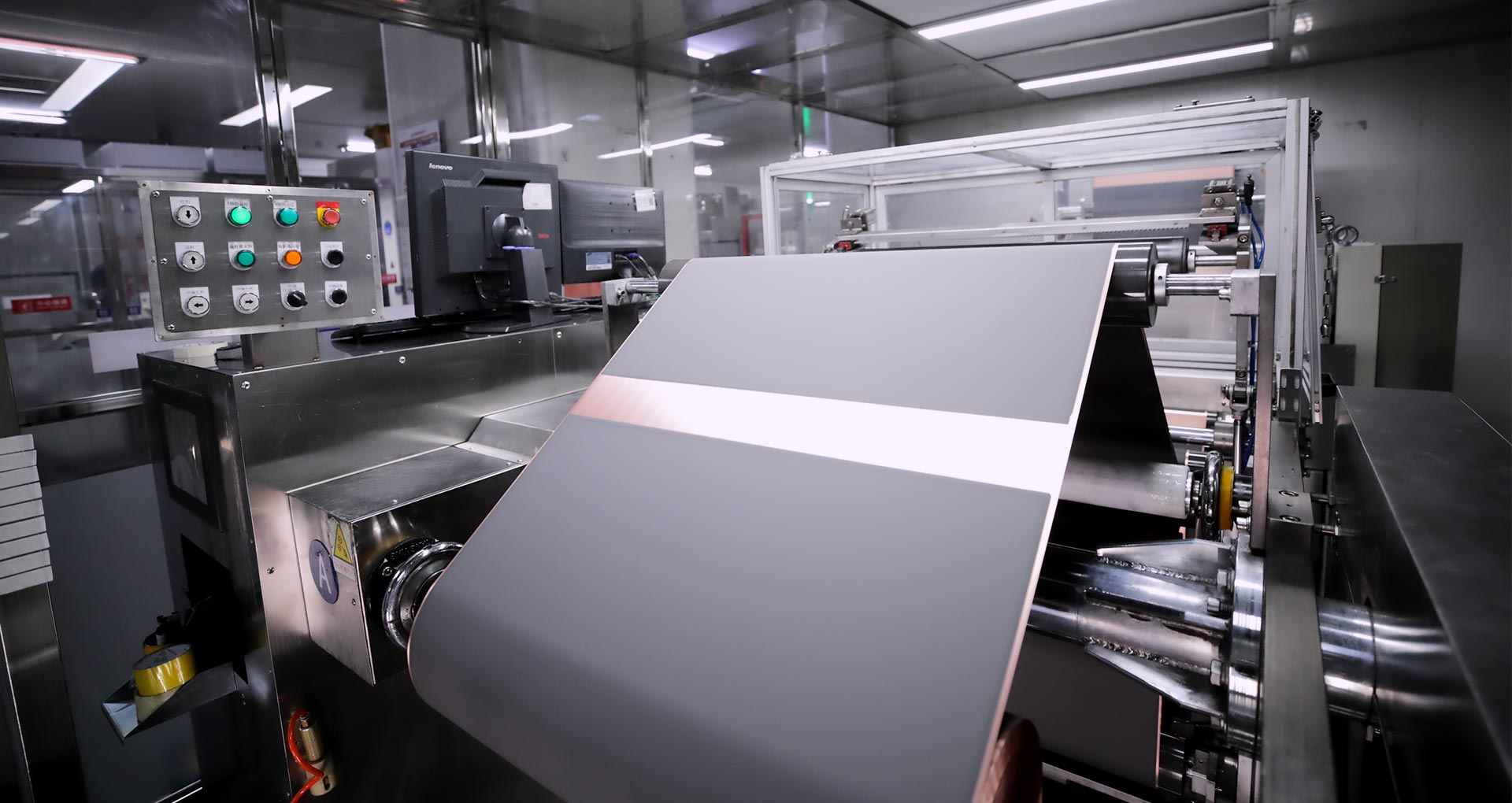
Electrode manufacturing begins with slurry preparation, where active materials, conductive additives, binders, and solvents are mixed into a uniform slurry. The cathode slurry is coated onto aluminum foil, while the anode slurry is coated onto copper foil through the electrode coating process.

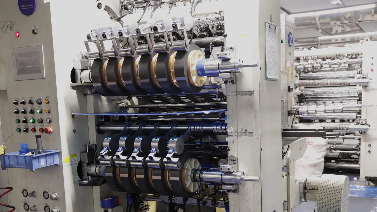
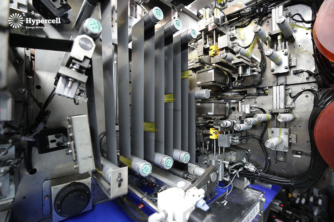
The coated electrodes then undergo drying to remove residual solvents, followed by calendaring to achieve the required thickness and electrode density. The electrodes are subsequently processed through slitting to obtain precise widths required for cell assembly.

Before entering the assembly stage, the electrode sheets undergo vacuum baking to remove residual moisture. Strict moisture control ensures better battery safety, improved cycle life, and long-term reliability.

Stage 3: Cylindrical Cell Assembly

The positive electrode, separator, and negative electrode are precisely wound together to form a cylindrical jelly-roll structure. After winding, electrode tabs are welded to ensure reliable current collection. The jelly roll is then inserted into the cylindrical steel case

Next, a groove is mechanically formed near the top of the case during grooving to secure the internal structure, followed by electrolyte injection in a controlled low-humidity environment. After electrolyte injection, the cells undergo electrolyte soaking to ensure complete wetting of electrodes and separators, followed by controlled aging.

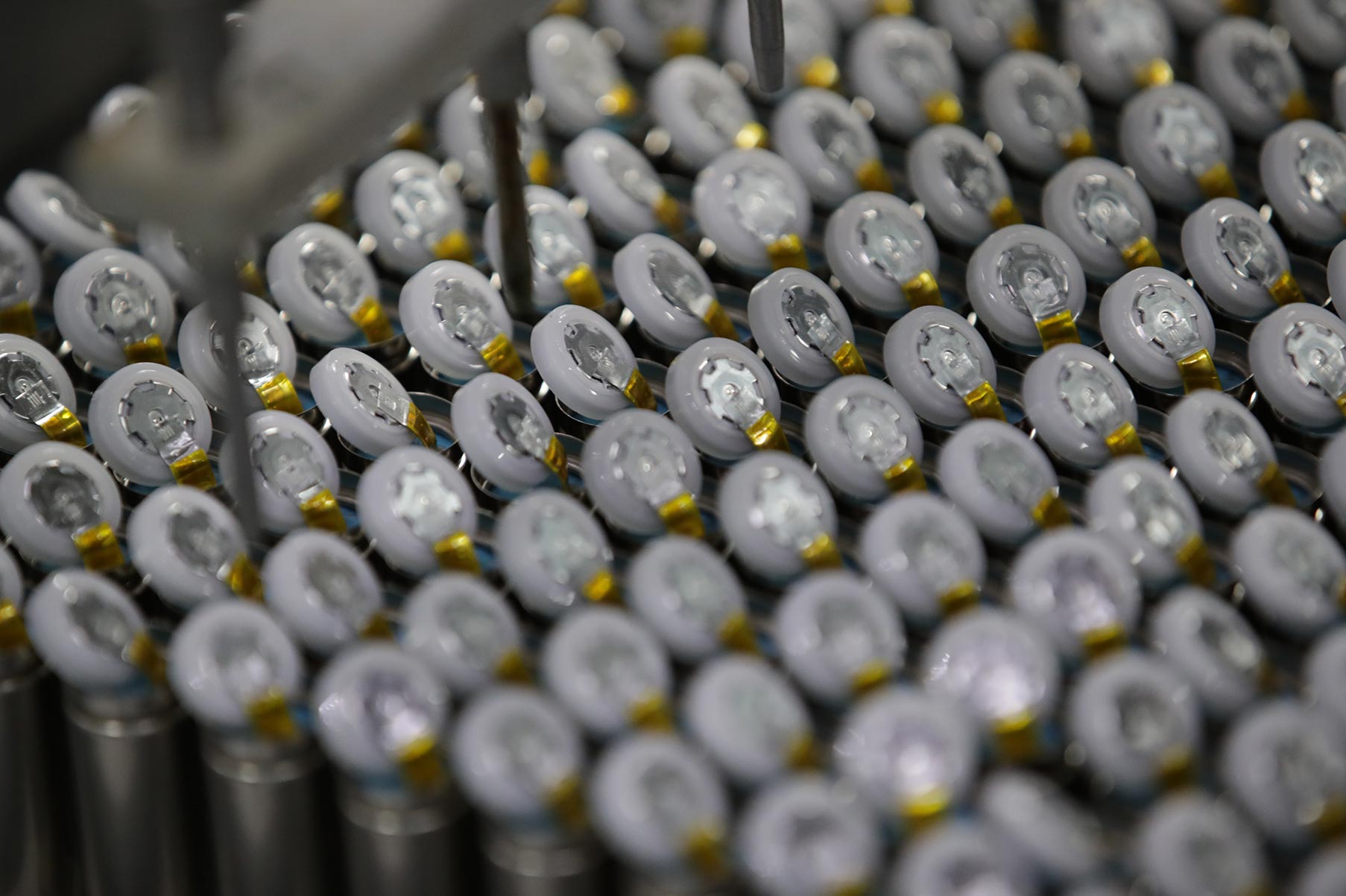
Finally, cell sealing is performed to hermetically seal the cell with a cap assembly that integrates a Current Interrupt Device (CID) and a safety vent, allowing the cells to safely proceed to the formation and testing stages.


Stage 4: Formation & Performance Testing

During formation, each cell undergoes controlled charge and discharge cycles to activate the electrochemical system and create a stable SEI layer on the anode surface. This process plays an important role in battery safety, cycle life, and long-term performance.

After formation, cells enter the aging stage under controlled environmental conditions. Aging helps evaluate voltage stability and identify potential defects before final inspection.

Each cell is tested for key parameters including capacity, voltage, internal resistance, and overall electrical performance. Cells are then graded according to performance characteristics to ensure consistency for battery pack assembly.

Stage 5: Digital Manufacturing & Traceability

Each battery cell is scanned and recorded through Hypercell’s MES-based digital production management system.

The traceability system tracks manufacturing information, inspection records, and production data to ensure complete quality control throughout the battery manufacturing process.

Digital traceability enables efficient quality management and supports reliable battery production for global customers.

Hypercell 18650 Battery Manufacturing Capability

As an experienced lithium-ion battery manufacturer, Hypercell provides customized cylindrical battery solutions from cell selection and battery design to mass production and quality validation.

Our capabilities include:

  • Cylindrical lithium-ion battery manufacturing
  • Custom battery pack development
  • Battery design support
  • BMS integration
  • Production quality control

With advanced manufacturing equipment, strict quality management, and complete production traceability, Hypercell delivers safe, reliable, and high-performance 18650 battery solutions.